
In simple terms, pitch diameter is the diameter of an imaginary cylinder that cuts through the thread, where the thread thickness equals the gap between threads; it is also called the effective diameter and controls how well bolts and nuts fit together.
What is the Pitch Diameter of a Thread? (Thread Pitch Diameter Explained)
When you look at a screw thread, you can see the outer crests and inner roots, but you cannot actually see the pitch diameter on the part. Pitch diameter is the size of an imaginary, coaxial cylinder that intersects the thread flanks exactly where the width of the metal and the width of the space between threads are equal.
Because it sits roughly halfway between the major and minor diameters, it is often described as the effective diameter of the thread.

In threaded fasteners, pitch diameter is the critical dimension that determines thread engagement, thread fit, and whether mating parts can be assembled smoothly under real production conditions. For that reason, most thread strength calculations, thread gaging practices, and international thread standards are built around pitch diameter rather than just the outside diameter of a bolt or screw.
Thread Geometry Basics: Major Diameter, Minor Diameter, and Pitch Diameter
Thread geometry starts with three core diameters: major, minor, and pitch. The major diameter is the largest diameter measured across the crests of an external thread (like a bolt) or across the roots of an internal thread (like a nut), and it is what many people casually call the “bolt size.” The minor diameter is the smallest diameter, measured at the roots of an external thread or the crests of an internal thread.
Pitch diameter lies between these two, measured at the point on the flank where material thickness equals space thickness, forming that imaginary pitch cylinder through the thread profile. Together, these three diameters define thread profile, load‑bearing area, and how the internal and external threads will share load once the joint is tightened.
Why Pitch Diameter Matters for Thread Fit and Fastener Performance
From a functional standpoint, pitch diameter is what truly governs thread fit and class of fit (for example, 2A/2B or 3A/3B). The allowance and tolerance on pitch diameter between the male and female threads determine how easily parts start, whether they wobble, and how much torque is required to assemble or disassemble the joint.
If the pitch diameter on an external thread is too large, the screw may bind or seize; if it is too small, the connection can feel loose and may not hold preload under vibration.
Thread strength calculations for bolt and screw connections are usually referenced to the effective section at the pitch diameter, not the major diameter.
That means an error of only a few thousandths of an inch in pitch diameter can change how much load a threaded fastener can reliably carry, especially in high‑strength, specialty fasteners.
For customers running high‑speed assembly lines or using vendor-managed inventory and kitted hardware, consistent pitch diameter control directly translates into fewer cross‑threading issues, less rework, and better joint reliability.
You might want to read this article from GD&T Basics:
How to Calculate Pitch Diameter (Thread Pitch Diameter Formulas)
In design work, engineers usually start from standardized thread series (UNC, UNF, metric ISO) where basic major diameter, pitch, and basic pitch diameter are tabulated. For 60‑degree threads such as ISO metric and Unified threads, the nominal pitch diameter can be calculated from the major diameter and pitch using a formula of the form “pitch diameter equals major diameter minus a constant times the pitch.”
One common relationship for single‑start 60‑degree threads is that the pitch line lies where the distance between the opposite flanks equals half the pitch, tying the effective diameter directly to the thread angle and pitch.omnicalculator+4
As a simple example, suppose an engineer has a Unified screw size with a known major diameter and pitch; by applying the standard formula or using a pitch diameter calculator, they can determine the basic pitch diameter and then apply the chosen tolerance class (such as 2A or 3A) to get maximum and minimum limits for manufacturing.
In practice, most teams rely on CAD, CAM, and online calculators to generate pitch diameter values rather than computing them manually for every thread size.
This approach reduces errors and ensures that thread dimensions remain consistent with ASME and ISO fastener standards.
How to Measure Pitch Diameter (Gaging and Inspection Methods)
Unlike a simple outside diameter, pitch diameter cannot be measured directly with standard calipers. Instead, metrology uses specialized methods that contact or infer the pitch cylinder at the flanks of the thread, not just at the crests.
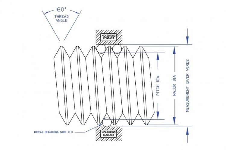
Image Source: https://vermontgage.com/support/detail/thread-measuring-wires-per-asme-b89-1-17
A widely used technique is the three‑wire method, where three precision wires sit in the thread grooves and a micrometer measures over the wires; a formula then converts this reading into the actual pitch diameter.
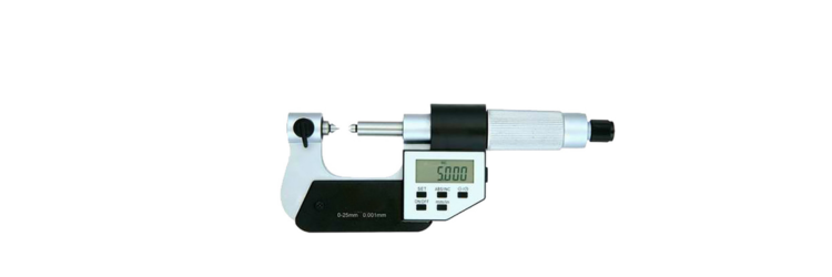
Thread micrometers provide a quicker, shop‑floor‑friendly way to check external thread pitch diameters using anvils shaped to fit the thread flanks.
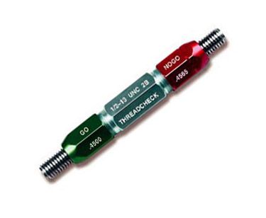
Image Source: Thread Check, Inc
For production, go/no‑go thread plug and ring gages provide a functional check that the pitch diameter and thread form are within the specified limits, even though they do not directly display a numerical pitch diameter.
Increasingly, automated optical inspection systems also scan thread profiles and compute pitch diameter digitally, supporting 100% inspection in high‑volume fastener programs.
Pitch Diameter Tolerances, Thread Classes, and Quality Standards
Thread tolerances define how much the pitch diameter is allowed to vary from its basic size. In the Unified inch system, external threads are designated 1A, 2A, or 3A and internal threads 1B, 2B, or 3B; class 1 has the loosest fit, class 2 is the standard commercial fit, and class 3 is a tight precision fit.
For example, for a given size, a 3A bolt has a smaller pitch diameter tolerance than a 2A bolt, providing less play but requiring tighter process control.
Metric ISO threads use tolerance positions and grades such as 6g or 6H to control pitch diameter and crest diameter ranges for external and internal threads.
A higher tolerance grade number generally means a broader tolerance band, roughly analogous to going from a precision 3B fit toward a more commercial 2B style fit. ISO‑certified fastener suppliers design their processes and gaging plans around these pitch-diameter limits to maintain capability and ensure that threaded fasteners in vendor-managed inventory bins assemble as intended.
Applying Pitch Diameter Concepts in Fastener Selection and Vendor Managed Inventory
For design engineers and purchasing teams, understanding pitch diameter helps in selecting the right thread form and class of fit for each application, from general‑purpose bolts to aerospace‑grade specialty fasteners.
A slightly looser pitch diameter fit (such as 2A/2B or a broader metric tolerance) can make sense where dirt, coatings, or field assembly are factors, while tighter fits (3A/3B or fine metric grades) are preferred where precision, repeatability, and vibration resistance are critical.
Coatings like zinc plating or galvanizing add thickness to the thread flanks, so engineers often specify an undersized pitch diameter on the raw part so the finished, coated fastener still meets the target class of fit.
When a fastener supplier manages a customer’s inventory and builds hardware kits, controlling pitch diameter within specification minimizes assembly problems at the line, especially with automated drivers and robots that depend on consistent thread engagement.
Robust pitch‑diameter inspection, combined with ISO‑based quality systems, helps ensure that the right fastener, in the right quantity and packaging, arrives ready for on‑time installation without thread‑related surprises.
